Two driving circuits and solar tracker control
Control circuit for solar tracker - diagram and description -
As already mentioned in another section of the site were taken into account two types of circuit to be combined with the mechanics of our solar tracker, the first to which went our preference unpublished and completely original (we found nothing similar on the net) purely electromechanical with switches and relays, the second most classic with photoresistors, operational amplifier and a few other components, rejected but still following some test properly working.
On this page you will find description and principles of operation of both with indication of how to achieve them.
Foreword, both circuits need a timer type "CN 101A" or other model with the same characteristics or 12 or 24 Volt DC power supply and for the control circuit with switches and relays the possibility of programming at least 15 events in fixed hours over a day.
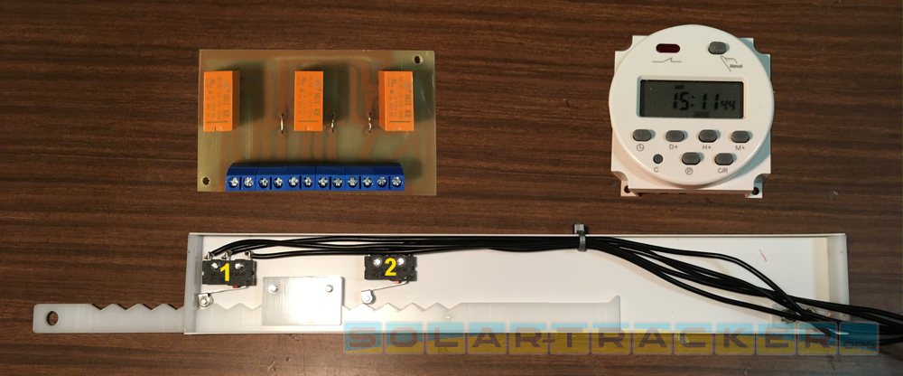
[ With these simple components you can control the rotation of the solar panel Switch 1 on/off at each cam crest - 2 on only at end run ]
- Description and realization of electromechanical solar tracker control circuit -
This system is based not on the positioning given by the sunlight that hits the sensors but by the timeframes set by the timer that make the actuator move to preset steps by the linear cam that, integral to the actuator during its run go to press the first switch stopping the movement, these movements will take place according to the times set in the timer.The second switch is used as a limit switch to return the linear actuator piston to the fully retracted position ready to receive morning sunlight the next day.
The basic scheme and the photos you find on this page will help you to better understand the operation, in addition to the switches are needed three relays connected as in the diagram, the 12 volt lamp fitted to the circuit can be from a minimum of 10 Watts to a maximum of 21 Watts and has been used as a simple but functional system to avoid excessive starting currents especially for when the piston of the linear actuator reaches background and there is an immediate rotation reversal, this causes a peak of current that causes a short ignition of the bulb that with the increase of its resistance goes to cut the peak of current itself obtaining a more soft inversion of orientation.
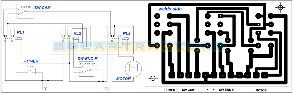
[ Relay microswitch connections diagram and drawing of printed circuit tracks for relays as our prototype ]
With this system it is not necessary a second waterproof container with transparent window for the sensors, usually this container must be fixed to the panel in order to follow the rotation of the sun, the lack of this container in appearance a minor detail is actually quite important as it deletes the problem of overheating of electronics in summer days, In addition there is to find the transparent plastic for the sensor window that if not proper after a few months of sunshine will become opaque (cause UV rays) sending the system into error.
Another advantage is that the electromechanical system is completely insensitive to extreme weather conditions; strong cloudiness, fog, lightning, rain on sensors or at critical placements, For example, near branches of wind-powered trees that can cover the sensors, causing the tracking system to fail.
The part that requires a bit of precision in the realization is the small strip of plastic material of thickness not less than 3 mm equipped with ridges and length calculated according to the stroke of the linear actuator, this strip will be enclosed in an "L" profile aluminum or pvc with small rectangular cutouts that make it slide guided in extension and retraction following the actuator while the switch will switch the supply voltage following the ridges. For the relay circuit it is advisable to use a millephous base on which to salt 3 relays type DPDT or two separate contacts placed in switching and possibly as in our solar tracker a terminal block to tighten the connecting wires to the various parts.
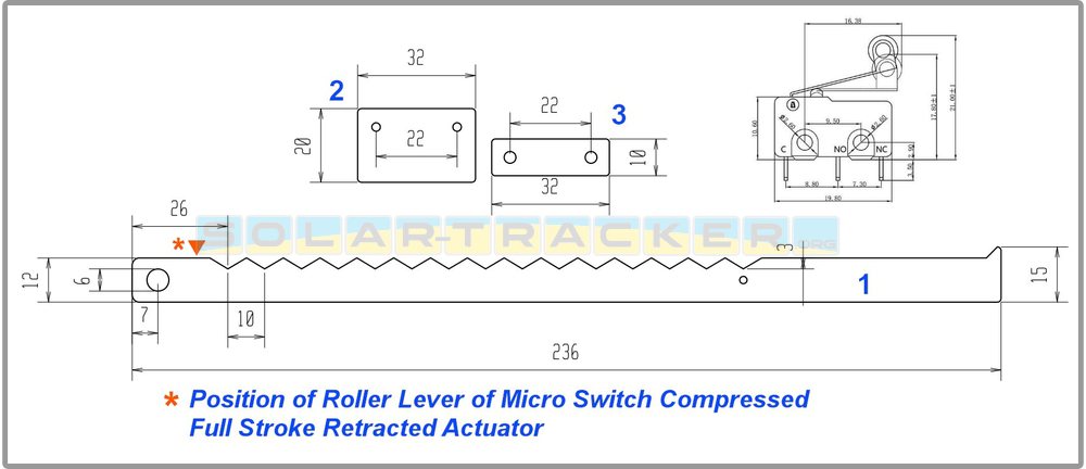
[ Parts 2 and 3 were fixed by M3 screws on the "L" profile to guide the linear cam ]
For dimensions and links follow the photos and diagrams on the page.
- Example program for our solar tracker with timer -
To manage the rotation of the panel, the possibility of the CN101 timer or another with the same characteristics will be used to control 16 (but 15 are enough for us) events with tripping of the relay at pre-set times.
In practice, with each intervention of the relay the actuator extends the line by a small step, thus rotating the panel throughout the day. In the program described here, the first intervention occurs from 08.30 to 09.10 a.m. NOTE: even when the timer turns off the linear actuator takes a step making the panel make another small rotation, in the timer setting sequence the times listed are relative to the relay in the ON state.
a.m. 08.30/09.10 - 09.45/10.15 - 10.45/11.10 - 11.35/11.55 - 12.10/12.25 - 12.40/12.50 - 13.00/13.20 - 13.30/13.40 - 14.05/14.20 - 14.40/ 3.00pm -
3.20/3.45pm - 4.10pm/4.40pm - 5.10pm/5.40pm - 6.20pm/7.05pm - 9.00pm/9.10pm
NOTE: in the time period 21.00/21.10 the arm of the linear actuator goes to the end of its stroke and then begins to retract to return to the initial position in the morning, it will remain in a state of rest throughout the night until starting the cycle again at 08.30 the following morning, the timer must be set to repeat the program daily seven days a week.
- Description and realization of solar tracker control circuit with photoresistors, transistors and operational amplifier -
The second circuit makes use of an operational amplifier used as a comparator, that is, when the brightness with the shift of the sun on the first photoresistor will be higher than a threshold value compared to the second photoresistor, the output of the operational amplifier will polarize the transistor that going into conduction will activate the relay and through its contacts will supply power to the linear actuator until with the rotation of the panel the sensor will return in shade. Peculiarities of the circuit are the three trimmers, two connected in series to the photoresistors to be calibrated so that these receiving the same light have the same resistance value (Ohm). Such trimmers are necessary for a greater precision as the photoresistors even if of the same nominal value of resistance cause tolerances of sensitivity can have differences of Ohm also quite high at the same light, The third trimmer is dedicated to the regulation of the circuit hysteresis so that at small variations of light there are no indecisions (switching vibrations) in the relay drive.
The scheme makes use of a second relay that will interface with the timer to allow the return to the initial position of the solar panel waiting for dawn the next day. Also this circuit given the simplicity it can be made on a board for millephous printed circuit boards following the diagram and the photos dedicated to it that you will find on this page.
![]()
[ Diagram and component list of solar tracker circuit with operational amplifier and photoresistors ]
Short video where the solar tracker circuit equipped with LDR (Light Dependent Resistor) sensors with two light intensities is tested to simulate the presence of full sun or sky with clouds.
In the video an extension of the wall that divides the sensors is also tested in order to increase their sensitivity to movements, the same result can be obtained by mounting the sensors closer together.
The peculiarity that makes this solar tracker circuit original is that in addition to not using an Arduino chip, it rotates in only one direction.
This choice was made given that the sun rotates in a single direction so it is useless to foresee the possibility of repositioning. going back, this will avoid false positioning as well as simplifying the circuit.
The return is managed by the timer described in these pages, in the video simulated by the On/Off switch.

